
When assessing LoRa devices' security, like any other RF technology, we must deal with unknown radio parameters and data/payloads we need to understand to complete our mission. Moreover, understanding these parameters and data may help to find interesting issues to exploit (clear-text communication, weak keys, stack protocol vulnerabilities). In this post, we will briefly present LoRa and its different security modes, and then we will focus on RF techniques to detect, demodulate and decode LoRa signals. Additionally, we will introduce some scripts we have made to decode, generate LoRa PHY and MAC payloads, Bruteforce keys and finally, fuzz some protocol stacks.
LoRA (Long Range) is LPWAN (Low-Power Wide-Area Network) technology that is used in many cases:
This technology uses license-free Sub-GigaHertz bands:
An exhaustive list of frequencies per country can be found here.
LoRa is used for long-range transmissions. Theoretically, we can expect the following ranges depending on different factors (indoor/outdoor gateways), as well as the environment:
See also 11 Myths About LoRaWan.
LoRa devices generally use two layers. The first one is called LoRa PHY, the proprietary lower physical layer. This part was made by Semtech and is proprietary, so there is no freely available documentation of this layer. However, Semtech has provided an overview of the modulation and some specifications. As this layer is proprietary and the only references are the provided specification, it is possible to encounter incompatible devices in practice.
The second layer is LoRaWAN, the cloud-based MAC (Medium Access Control) layer protocol. This layer communicates between LPWAN (Low-Power Wide-Area Network) gateways. The following picture shows the classic architecture of a LoRaWAN network:
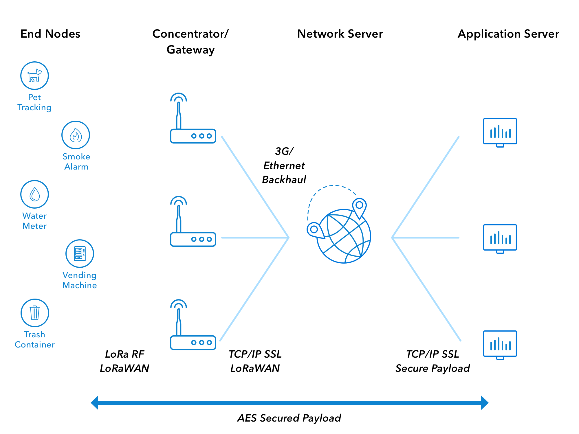
LoRaWAN is not mandatory when using a LoRa device. It is also possible to use raw MAC communication to send commands and messages directly like in P2P (Peer-to-Peer) for example. But in this case, 100% of the security remains in people's hands, as it does not provide encryption and integrity as LoRaWAN does.
LoRa equipment can have various security modes:
The raw MAC does not provide any security by default. Therefore, devices set to this configuration could be vulnerable to eavesdropping and injection. On the other hand, devices using the LoRaWAN stack can be set with ABP or OTAA activation methods.
The rest of this section will briefly speak about LoRaWAN 1.0 and 1.1 security, specifically its keys.
The preferred and most secure method is OTAA. Indeed, within this mode, a Join procedure is mandatory to authenticate the LoRa end-device:
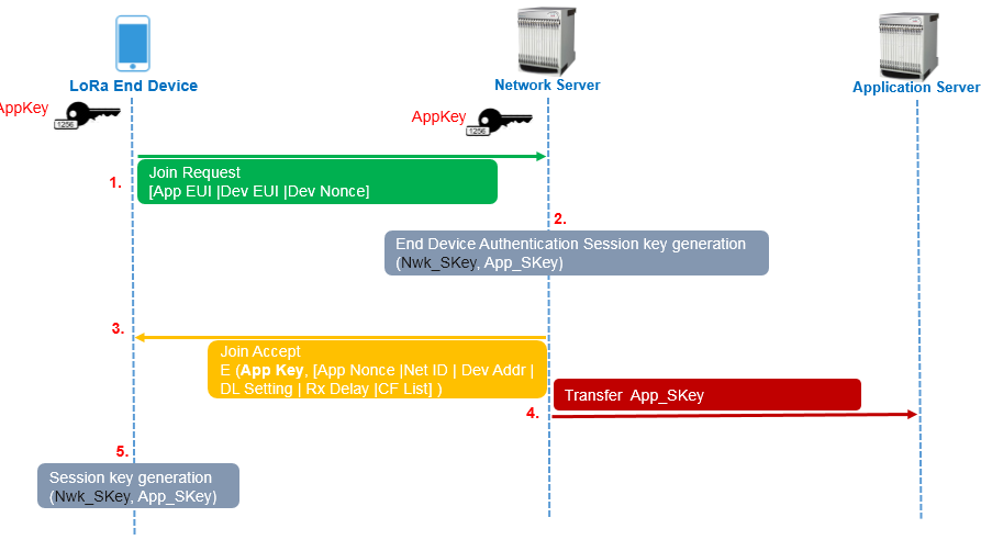
In this process, the end device first sends a Join-request with 3 parameters to derive the session keys:
These 3 parameters are sent in clear text, but a MIC (Message Integrity Code) value is included in the message, and if we refer to LoRaWAN version 1.0, we see that it is computed as follows:
cmac = aes128_cmac(AppKey, MHDR | AppEUI | DevEUI | DevNonce)
MIC = cmac[0..3]
The MIC is a 4 bytes AES-128 CMAC and uses an AES-128 key, called AppKey, to cipher public information. The end device and the application only know the AppKey.
If the device is permitted to join the network, session keys are generated on the Network side. After that, a Join-accept is then sent by the network to the end device with 6 parameters that are encrypted with the AppKey:
The Join-accept payload is encrypted as follows:
aes128_decrypt(AppKey, AppNonce | NetID | DevAddr | DLSettings | RxDelay | CFList | MIC)
Note: The network uses AES decrypt in ECB mode to encrypt messages, that the end device will decrypt with an encryption method.
And session keys are computed as follows on the network and the end device sides to protect data confidentiality and integrity:
NwkSKey = aes128_encrypt(AppKey, 0x01 | AppNonce | NetID | DevNonce | pad16)
AppSKey = aes128_encrypt(AppKey, 0x02 | AppNonce | NetID | DevNonce | pad16)
In the end, the NwkSKey will be used to compute and verify messages integrity with the MIC field, and AppSKey will be used to encrypt and decrypt messages.
LoRaWAN 1.1 provides more robustness than version 1.0, as it ensures the rotation of keys by relying on multiple session keys to protect the data in confidentiality and integrity.
In fact, the Join procedure is the same but use a dedicated key called NwkKey to generate the MIC value:
cmac = aes128_cmac(NwkKey, MHDR | JoinEUI | DevEUI | DevNonce)
MIC = cmac[0..3]
This same key is used to encrypt the parameters of the Join Accept message:
aes128_decrypt(NwkKey, JoinNonce | NetID | DevAddr | DLSettings | RxDelay | CFList | MIC)
The AppSKey is generated like in LoRaWAN 1.0 if the OpNeg bit of the DLsettings field is set. The OpNeg bit is used to negotiate LoRaWAN protocol to version 1.0 when it is set. Otherwise, 1.1 version is used.
Compared to version 1.0, two other keys FNwkSIntKey and SNwkSIntKey are generated for uplink and downlink messages MIC integrity ,respectively. Moreover, NwkSEncKey replaces the NwkSKey to protect MAC commands transmitted as payload on port 0, or in the FOpts field.
When OpNeg is not used, these keys are computed as follows:
FNwkSIntKey = aes128_encrypt(NwkKey, 0x01 | JoinNonce | JoinEUI | DevNonce | pad16 )
SNwkSIntKey = aes128_encrypt(NwkKey, 0x03 | JoinNonce | JoinEUI | DevNonce | pad16)
NwkSEncKey = aes128_encrypt(NwkKey, 0x04 | JoinNonce | JoinEUI | DevNonce | pad16)
Version 1.1 also implements a ReJoin-request that will generate keys dedicated for this purpose:
JSIntKey = aes128_encrypt(NwkKey, 0x06 | DevEUI | pad16) # for integrity
JSEncKey = aes128_encrypt(NwkKey, 0x05 | DevEUI | pad16) # to encrypt Join Accept payload
And so the MIC will be computed as follows for the next data exchanges:
cmac = aes128_cmac(JSIntKey, JoinReqType | JoinEUI | DevNonce | MHDR | JoinNonce | NetID | DevAddr | DLSettings | RxDelay | CFList )
MIC = cmac[0..3]

If you want to learn more about changes from LoRaWAN 1.0 to LoRaWAN 1.1, please look at Renaud Lifchitz's presentation made at The Things Conference 2019.
The ABP method is more straightforward than OTAA, as there is no Join Procedure. Nevertheless, it has downsides in terms of security, as session keys are hardcoded on 1.0 version as for 1.1.
Indeed, session keys stay the same until we manually change it, or with a firmware update/upgrade, so ABP could be more vulnerable to a cryptanalysis attack than OTAA.
Using ECB mode encryption is risky as the ciphertext can leak information about the plaintext (length, prefixes, common substrings, etc.). Renaud Lifchitz has discussed this problem at Hardwear.io 2016. During the talk, Renaud also mentioned that some devices have unprotected memory, and it is possible to get the firmware and its configuration by interfacing ourselves with the device. Furthermore, he also mentioned that it is possible to impersonate gateways that are not authenticated.
In addition to these issues with LoRa version 1.0, we also weak keys AppKey and hardcoded AppSKey and NwkSKey. Indeed, in OTAA it is possible to enumerate weak/default AppKey key on Join-request's MIC field and Join-accept payloads. After recovering the AppKey with a brute-force, an attacker may be allowed to impersonate an end device and eavesdrop on communication if he can intercept the whole Join procedure. In ABP mode, it is even worse, as an attacker retrieving the AppSKey and NwkSKey for devices can eavesdrop on the communication anytime he wants.
Data security in LoRaWAN generally relies on decent key management procedures. About that, there is an excellent guide written by ex-MWR Labs, currently F-Secure Labs, that explains mistakes made in different components and how to improve their security.
We can briefly highlight some general practices to apply to a LoRaWAN setup:
To intercept LoRa signal, we will use a Software-Defined Radio device and GNU Radio to make the signal acquisition. For our case, we use a USRP B205mini-i, but that could be pretty any device, even an RTL-SDR, with GNU Radio support.
When dealing with unknown targets, we must go through several stages until we can capture and analyze their data.
So let's start by scoping targeted frequencies!
At this stage, we need to know the frequencies used by our target. To do that, we can use a waterfall to represent the signal across the frequency range and an FFT (Fast Fourier Transform) block to find the different frequency components of a signal. Here is a GNU Radio schema that can achieve that:
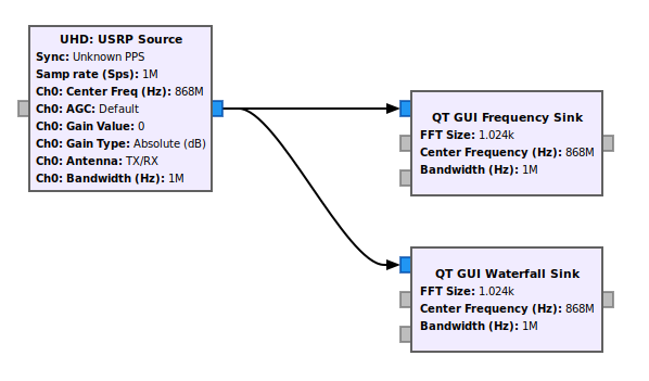
In this schema, the sampling rate samp_rate can be increased depending on your SDR device. Of course, the longer it is, the more range you will cover, but then you'll have to process it with your computer (be wise). Moreover, the central frequencies can be changed with a slider block implemented in GNU Radio to cover the different bands dynamically.
Note: The identification of signals can also be performed with tools like GQRX or other RF explorer tools. But for this post, we will keep using GNU Radio and evolve our schema to the end.
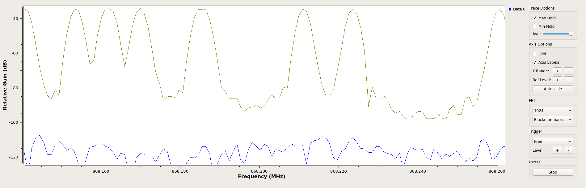
It is also essential to fill the Max Hold box on the FFT display to keep track of frequency components. Here is the result when a signal is triggered:
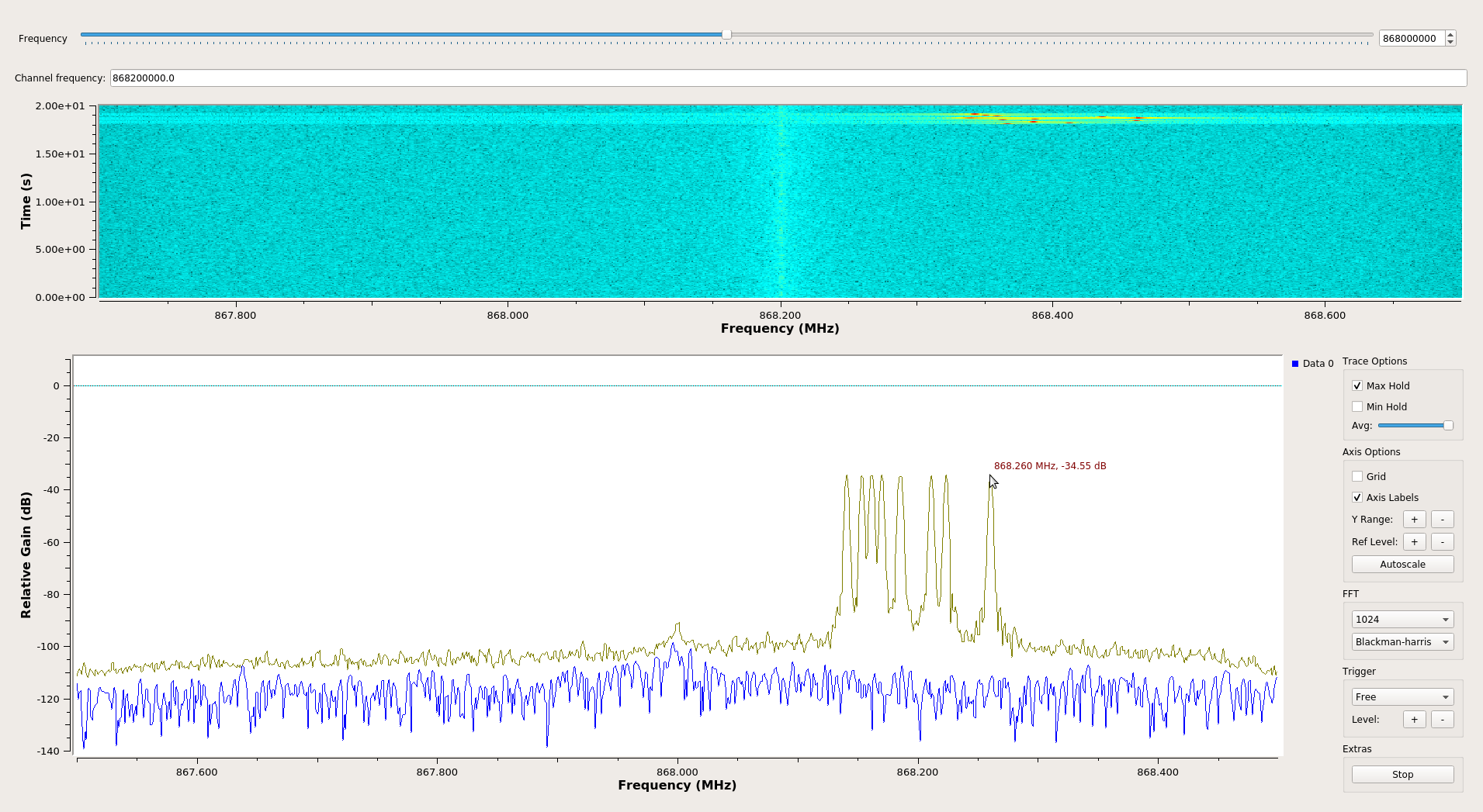
In the above screenshots, we can observe that a signal was sent 868.2 MHz central frequency. Looking at the lower and highest frequency components of the FFT, this signal should have a bandwidth of 125 kHz:
It should be noted that LoRa devices generally use multiple channels, and so it is better to identify all of them the same way before going further.
In the previous section, we identified an exciting signal with multiple short chirps that we can observe on the waterfall part above the FFT. Let's now demodulate and decode it.
To transmit signals LoRA uses a proprietary spread spectrum method derivative to CSS (Chirp Spread Spectrum) and FEC (Forward Error Coding) to improve resilience against interference. A very good resource can be found on this RevSpace page. Thanks to gr-lora of Bastille and gr-lora of rpp0, the demodulating and decoding of LoRA PHY signal can be done quickly with one of the 2 modules. For this post, we will use gr-lora of rpp0 as it is well and nicely maintained but also easy to install with GNU Radio 3.8.
To continue, we add a LoRa Receiver from gr-lora to our schema, but at this stage, we have to fill different parameters:
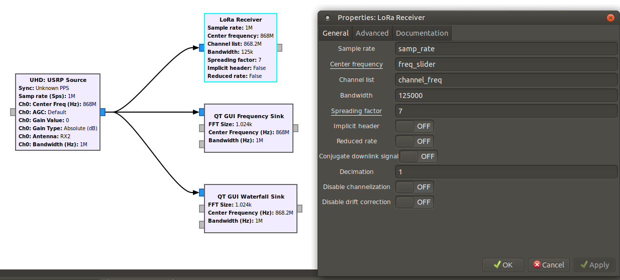
We already know the frequency channel used by our captured signal, 868.2 MHz, and the BW (bandwidth). However, there is still the SF (Spreading Factor) value left. To find what kind of values it could take, we can look at SF and BW used for LoRa online table and focus on European countries for our case:
Data Rate           Configuration   bits/s  Max payload
-------------------------------------------------------
DR0                 SF12/125kHz     250     59
DR1                 SF11/125kHz     440     59
DR2                 SF10/125kHz     980     59
DR3                 SF9/125kHz      1 760   123
DR4                 SF8/125kHz      3 125   230
DR5                 SF7/125kHz      5 470   230
DR6                 SF7/250kHz      11 000  230
DR7                 FSK: 50kpbs     50 000  230
Naively brute-forcing this missing SF parameter is a way, among others, but we can think about more innovative moves. Indeed, as seen in the table above, LoRa operates with SF from 7 to 12. So the shorted chirp is SF7 with a data rate of 11 kilobits/s, and 12 the longest with a data rate of 250 bits/s. So by consequences, this will affect on time, and this can be observed if we compare two configurations, one with an SF7 and 125 kHz BW (on the left) and our target (on the right):
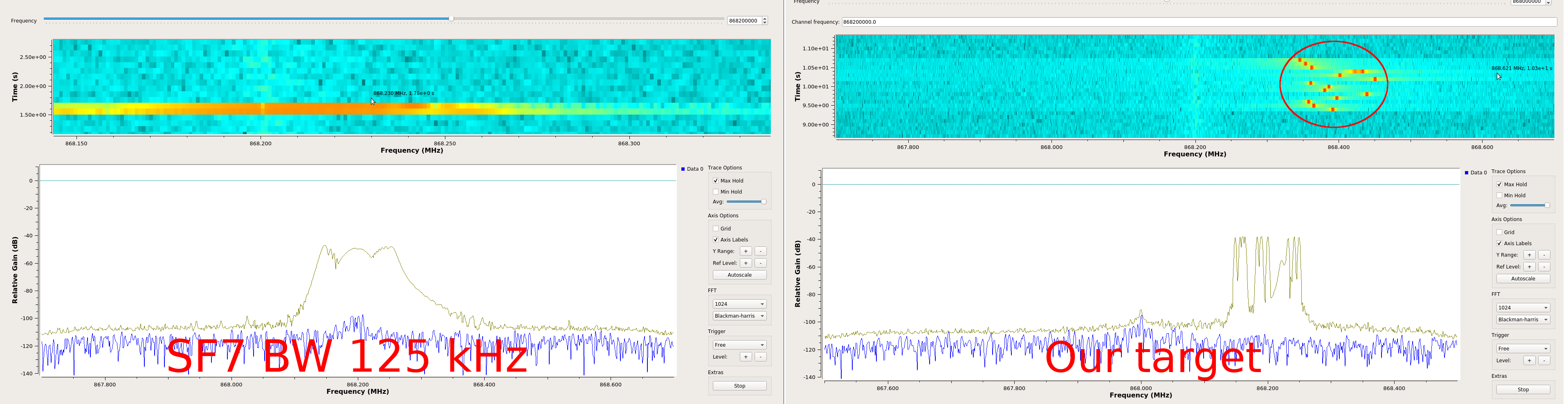
As shown in the above figure, chirps are sent faster in the SF7 configuration than our target, so our target probably uses one of the highest SF configurations.
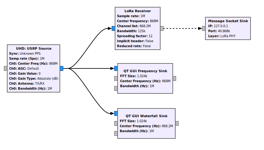
So by changing the receiver to SF12BW125 configuration, we are finally able to see packets in GNU Radio console as follows:
18 31 10 40 ad 15 00 60 00 00 00 03 ca fe ff ff ff ff ff ff ff ff ff 6e 5a d7 0d 59 2e
But these hexadecimal does not mean anything to us now, apart from the word 0xcafe (french word for coffee - Deuh).
So for further analysis, we have made a few tools to parse these packets.
After being able to capture, demodulate and decode LoRa PHY signal, we need to understand the structure of these packets. For LoRaWAB 1.0 a tool called lorawan-packet-decoder has been published, but this is not very flexible for our case and does not allow us to generate packets for different purposes.
We have made Scapy layers to parse LoRa PHY packets decoded by the GNU Radio g-lora receiver. This layer can be fetched on our GitHub here.
As an example, if we take the previous packet retrieved by the receiver, we can decode it as follows:
>>> import binascii
>>> from layers.loraphy import *
>>> pkt = "18 31 10 40 ad 15 00 60 00 00 00 03 ca fe ff ff ff ff ff ff ff ff ff 6e 5a d7 0d 59 2e"
>>> l_pkt = LoRa(binascii.unhexlify(pkt.replace(" ", ""))
... )
>>> l_pkt.show()
###[ LoRa ]###
  Preamble  = 0x1
  PHDR      = 0x8311
  PHDR_CRC  = 0x0
  MType     = Unconfirmed Data Up
  RFU       = 0
  Major     = 0
  \DevAddr   \
   |###[ DevAddrElem ]###
   |  NwkID     = 0xad
   |  NwkAddr   = 0x600015
  \FCtrl     \
   |###[ FCtrl_UpLink ]###
   |  ADR       = 0
   |  ADRACKReq = 0
   |  ACK       = 0
   |  ClassB    = 0
   |  FOptsLen  = 0
  FCnt      = 0
  FPort     = 3
  DataPayload= '\xca\xfe\xff\xff\xff\xff\xff\xff\xff\xff\xff'
  MIC       = 0x6e5ad70d
  CRC       = 0x592e
The module gr-lora also implements a block to quickly send packets other UDP to an arbitrary host and port, so we will use to send packets to a port that will be caught by the Scapy sniff() function later:
To get UDP packets locally and interpret them automatically, we can use a script called LoRa_PHYDecode.py of the Lora Craft repository:
$ python LoRa_PHYDecode.py
<LoRa  Preamble=0x1 PHDR=0x631e PHDR_CRC=0x0 MType=Unconfirmed Data Up RFU=0 Major=0 DevAddr=[<DevAddrElem  NwkID=0xad NwkAddr=0x600015 |>] FCtrl=[<FCtrl_UpLink  ADR=0 ADRACKReq=0 ACK=0 ClassB=0 FOptsLen=0 |>] FCnt=0 FPort=2 DataPayload='i\x06D\x94\x97\x08\xce!\xd9' MIC=0x4b516899 CRC=0x96e1 |>
...
<LoRa  Preamble=0x1 PHDR=0x631e PHDR_CRC=0x0 MType=Unconfirmed Data Up RFU=0 Major=0 DevAddr=[<DevAddrElem  NwkID=0xad NwkAddr=0x600015 |>] FCtrl=[<FCtrl_UpLink  ADR=0 ADRACKReq=0 ACK=0 ClassB=0 FOptsLen=0 |>] FCnt=0 FPort=2 DataPayload='penthertz' MIC=0x20a5fcba CRC=0xcdc |>
<LoRa  Preamble=0x0 PHDR=0xd30c PHDR_CRC=0x0 MType=Confirmed Data Up RFU=0 Major=0 DevAddr=[<DevAddrElem  NwkID=0xad NwkAddr=0x600015 |>] FCtrl=[<FCtrl_UpLink  ADR=0 ADRACKReq=0 ACK=0 ClassB=0 FOptsLen=1 |>] FCnt=0 FOpts_up=[<MACCommand_up  CID=LinkCheckReq LinkCheck=[''] |>] FOpts_down=[<MACCommand_down  CID=222 |>] FPort=92 DataPayload='' MIC=0x31c753f |>
In OTAA, the Join procedure could be interesting to capture and brute-force MIC fields on Join-request messages. As we saw earlier, this MIC is generated by the AppKey in version 1.0 of LoRaWAN and the NmkKey for 1.1.
As an example, if we are able to intercept the following Join-request packet, we can test if a weak key like 000102030405060708090A0B0C0D0E0F with our lutil/crypto.py helper checkMIC:
>>> from layers.loraphy import *
>>> from lutil.crypto import *
>>> key = "000102030405060708090A0B0C0D0E0F"
>>> p = '000000006c6f7665636166656d656565746f6f00696953024c49'
>>> pkt = LoRa(binascii.unhexlify(p))
>>> pkt
<LoRa  Preamble=0x0 PHDR=0x0 PHDR_CRC=0x0 MType=Join-request RFU=0 Major=0 Join_Request_Field=[<Join_Request  AppEUI='lovecafe' DevEUI='meeetoo' DevNonce=26985 |>] MIC=0x53024c49 |>
>>> checkMIC(binascii.unhexlify(key), str(pkt))
True
Moreover, for Join-Accept messages, the AppKey or NwkKey can be tested by combining JoinAcceptPayload_decrypt and checkMIC:
>>> pkt = "000000200836e287a9805cb7ee9e5fff7c9ee97a"
>>> ja = JoinAcceptPayload_decrypt(binascii.unhexlify(key), binascii.unhexlify(pkt))
>>> ja
'ghi#\x01\x00\xb2\\C\x03\x00\x00{\x06O\x8a'
>>> Join_Accept(ja)
<Join_Accept  JoinAppNonce=0x6fe14a NetID=0x10203 DevAddr=0x68e8cb1 OptNeg=0 RX1DRoffset=0x0 RX2_Data_rate=0x0 RxDelay=0x0 |<Padding  load='\xbejsu' |>>
>>> p = "\x00\x00\x00\x20"+ja # adding headers
>>> checkMIC(key.decode("hex"), p)
>>> True
In ABP, bruteforce attacks against NwkSKey and AppSKey in version 1.0 can be performed against encrypted data payloads. However, in 1.1 version, bruteforcing would require more computing, as the MIC is generated by dedicated session keys for integrity, especially if we could not be able to recover known fields of an unencrypted Join-accept.
To test these sessions keys, you can use lorakeys as suggested in an interesting article written by Sébastien ROY (in French).
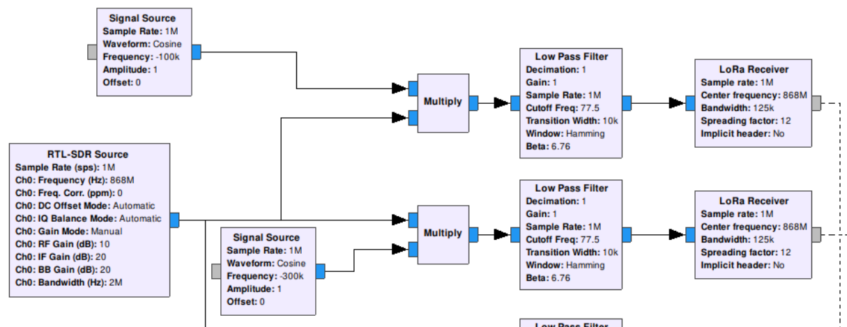
Heterodyning is a signal processing technique that shifts one frequency range into another. To perform that, an input signal (f1, for example) will be multiplied by a local oscillator (f2) with a mixer:

In addition, to signal f1, this process will produce two additional signals f1-f2 and f1+f2. This technique is generally used in all modern superheterodyne radio receiver.
In our cases, we will probably face multiple channels and use many LoRa receivers to decode all LoRa signals in the selected bandwidth. So to reduce all that, we can probably use this signals mixing technique to shift downlink and uplink messages of a channel to the exact center frequency. Tristan Claverie and José Lopes Esteves proposed this idea in their article called A LoRaWAN Security Assessment Test Bench, published in the European GNU Radio 2019 book.
Note: To be more efficient, a channelizer would avoid making mixer for each channel, and also save computing time.
Identifying, capturing, and decoding LoRa signals in practice seems essential, thanks to provided tools and the proper methodologies. Nevertheless, in a real scenario, attackers will face many other signals in targeted frequency ranges and noise and other elements that could disturb us during an assessment. Therefore, generally speaking, with RF, it is recommended to have a good feedback in a closed environment before going into the wild and trying to attack a target in production. Also, attacking keys can be very fruitful in some cases when there are manually set and weak. Otherwise, the attacker could also try to identify exposed internet services and find vulnerabilities in one of them to compromise nodes' keys.
We hope these tools and resources we made for this post will help to assess LoRa setups and invite you to contribute if you have some ideas ;)!
Don't miss our next training from the 10th to the 13th of February 2020 in Berlin:
